


 indicates a required field.


- MID Approved
- BMS output
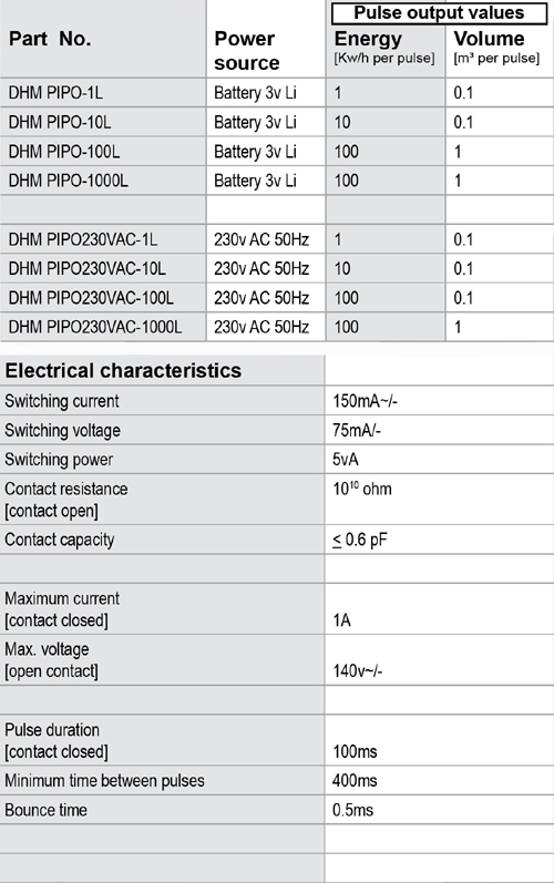
- Pulsed output [Kw/hr], M-bus or 4-20mA versions
- Dn 15-300 applications
- Battery or 230v AC versions
- IP65 protection rating
- EMC Class C according to EN1434
- Measurement range: 1 - 150°C
- Ambient temperature: 5 - 55°C
- Temperature resolution: 0.01°C
- Measuring frequency: 20 - 120 seconds
- No data loss when battery removed
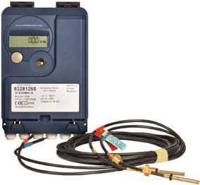
- PT500 sensors
- For use with Mechanical, Ultrasonic or Magflow meters
- Two pulsed inputs available as standard
Additional Features
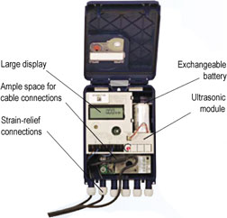
- Continuous display of the accumulated heat energy on a large LCD display
- Application-oriented display menu; easy to scan using operating key
- Data storage six times a day in non-volatile memory
- Hourly self-check
- 12 monthly values readable on the display or via the optional interface
- Available lengths of temperature sensors: 3m [2-wire type] and 10m [4-wire type]
- Installation in temperature pockets of various lengths possible.
Technical Data
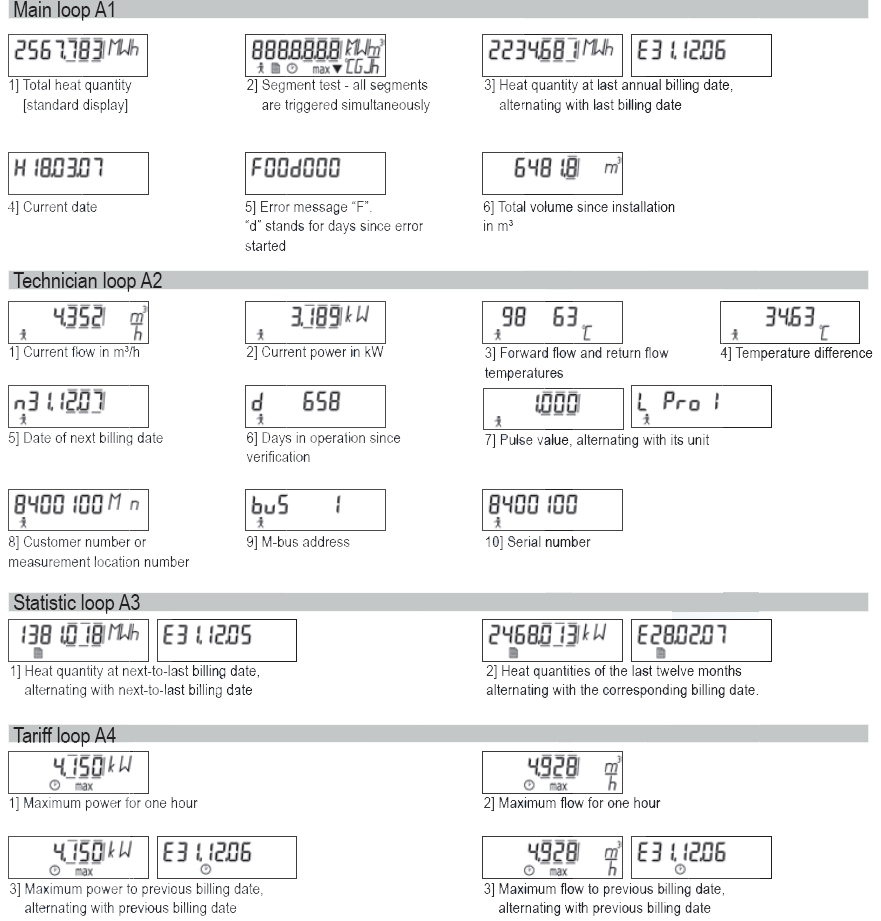
The Menu
The large high-contrast display continuously shows the accumulated heat energy. This enables an easy, sure and quick read-out of the most commonly needed figures.
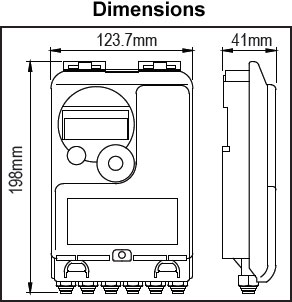
All sizes are approximate and are given for guidance only.
Products and specifications may be subject to change from those shown without notice.
Storage Instructions
Dry and frost protected
Dimensions
Mouting Instructions
- Affix the wall mounting bracket [supplied with the calculator] to the wall and clip on the calculator.
- Connect the wires as described below [for the pulsed BMS output].
- Clip the calculator on the output module
- Remove the terminal cover on the front of the calculator.
- Connect two wires from water meter to left hand terminal [NOT polarity sensitive] to give pulsed input flow rate.
- Re-fit terminal cover.
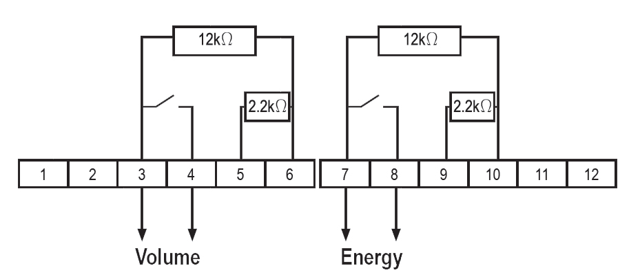
Connection of the pulse output unit
- To clamp on the pulse output for energy: the clamps 7 and 8 must be connected.
- The short circuit wire between 4 and 5 must be removed.
- To clamp on the pulse output for volume: the clamps 3 and 4 must be connected.
- The short circuit wire between 8 and 9 must be removed.
All sizes are approximate and are given for guidance only.
Products and specifications may be subject to change from those shown without notice.